 AC POWER 101, What Happens When Power Fails and What You Can Do About It AC POWER 101, What Happens When Power Fails and What You Can Do About It
by Robert Schwartz
We depend upon a stable, reliable source of power for our equipment, our computer, monitor, printer, tv, etc. Because of its reliability, we take it for granted. However, being in the real world, we have to accept that sometimes it will fail. How we deal with it when it fails is our subject.
Introduction
We will be dealing with a variety of terms, perhaps more than you thought there were or perhaps more than you want to know. As an example, we will dwell on terms such as: backup, uninterruptible power supply, grounds, grounding, lightning, surge suppressor, volts, amps, watts, power plugs, color codes, house wiring, time, nano-seconds, and on and on. In any case, dive in where you want or skip those you don’t.
For some, who backup their work-product automatically and frequently, failure can be more of an annoyance than a catastrophe. For others involved with a “mission critical” application, failure cannot be tolerated. For yet others whose circumstances lie between these extremes, an orderly shutdown may suffice. And none of us want to tolerate equipment damage or failure. Most importantly, we must address personal safety. We certainly do not want to risk being electrocuted or causing a fire. We will try to address some of the anomalies in power delivery and some of the things we can do about it. And, we will take a conservative approach, the minimum necessary to achieve the level of protection and safety desired.
Priorities, Goals
One of the first things we must do is to figure what is most important to us. Note: in all cases two things must be addressed (1) good grounding practice and (2) surge and spike suppression. These are necessary for equipment protection and personal safety.
If we back up frequently, then we may be able to tolerate the annoyance of a power failure. The last data we were working on since the last automatic backup will be lost. But we won’t have to add any more equipment to our system. And we can make the automatic backup fairly frequent. With Word or Excel, go to Tools, Options, Save and set the save interval.
UPS, CPU, safe shutdown
If we cannot tolerate loss of work product, but we do not have to continue working during a power failure, a small capacity UPS (uninterruptible power supply) will be needed. This should be sized to support the CPU (central processing unit) and monitor for a period at least longer than the system shut down time, and the UPS should be equipped to automatically shut down your system when it senses power failure. Run time, so your CPU and monitor can shut down, probably need be no more than 10 to 15 minutes. The more run time your UPS has, the more expensive it will be. Most UPS’s are equipped with surge suppressors so your other equipment can be connected to the surge suppressed outlets and not to the UPS sockets. In this mode of operation, you will have time for the system to safely shut down BUT you may not be able to continue operating, since none of the peripherals – the printer, the scanner, etc. will be powered. Here, the idea is a safe shutdown where your work product is saved, but not continued operation.
In case your system shuts down, wait about 5 minutes before rebooting. This is because the power company may employ automatic circuit reclosing. In case of a fault, power line equipment may automatically re-close up to 3 times in the hope that the fault may clear itself before it gives up. So, wait a bit before trying to start up again.
If continuing to operate is paramount, then a UPS (uninterruptible power supply) plus an auxiliary generator may be required. In this case, the UPS must support the load of your entire system for a period longer than it takes for the auxiliary generator to be started and brought up to speed. One point to make here. Your auxiliary generator is not as stable as utility power. Its speed and thus line frequency may vary with load. In this case a ferro-resonant type voltage regulator for the output of the auxiliary generator may not be a good plan because its output voltage is frequency (and thus speed) dependent. For operation on line-power from a utility, a ferro-resonant constant voltage transformer does an excellent job of maintaining a constant output voltage over a wide range of input voltage.
Aberrations- - surges, spikes, corrosion
The ready stable source of power may not always be there. In storms we encounter lightning which can produce surges and high amplitude spikes. If lightning strikes nearby, we can experience spikes and pulses high enough to damage equipment and endanger people. Fluorescent lights and equipment with switching mode power supplies such as computers can cause spikes on the line. Wind can topple trees which can cause power failure or, due to short circuits, can cause serious line surges. Corrosion or thermal loosening of electric outlet screws can cause lights to blink. If this affects the neutral conductors, some outlets can exhibit low line voltage and others can have higher than normal voltage. All of these we will try to address.
Cures (?)
We will try to address the various ways in which the aberrations can be controlled – surge arrestors, UPS – uninterruptible power supplies, single point grounding.
Theory or Technical Jargon
You can skip over this if you are not interested. But, if you do skip over it, you’ll just have to accept the various terms used, and assume that the writer knows what he’s talking about, and that you do too.
Intimidating Theory #1
Power plugs, color codes, circuit breakers, wiring, “hot”, “neutral”, “ground” leads, “daisy-chaining”
As we start, and as we look at a typical 120 VAC power plug, we see 3 projecting “pins” that plug into an electrical outlet. There are 2 “blades” and one round or “U” shaped pin. Looking at the pins head on, the left one, typically not as wide as the one to the right, is the “hot” lead. The wider blade is the neutral and the round or U shaped one is the ground lead. On the back side of electrical outlets, the brass or gold colored screw terminal connects to the “hot” lead. The wider spade connects to the neutral lead. On the backside of an outlet, the neutral lead connects to the silver colored terminal. The round or U shaped pin connects to the ground lead. The plug is designed, as you can see, so that the ground pin is longer than the spade terminals and thus makes contact in the socket before the spade terminals do. For safety, this grounds the device connected to the plug. On the back of the outlet, the ground terminal is usually off to the side and frequently has a green colored screw. Looking at the back of an electrical outlet, a standard “color code” identifies the individual conductors. The “hot” lead is usually either black or red, the “neutral” white, and the “ground” lead green.
The leads coming from the power pole are frequently black, red, and white (or black, bare, and black). Between the black and red, or black and black, are 230 – 240 volts and between either of them and the white or bare one is 115-120 volts. When these leads are brought in, they go first to the wattmeter and then to the circuit breaker panel. Some circuit breaker panels have 3 vertical copper bars, or buses as they are called. The neutral lead goes to the middle one and the black to one of the outside buses and the red lead to the other. On some panels some of the circuit breakers are connected to the left bus and some to the right bus where each delivers 115-120 volts. There are some other dual types that connect to both of the outside buses to deliver 230 volts. Each single breaker supports a 115-120 volt house circuit. The wire from each circuit breaker, black or red, is a “hot” lead.
On some breaker panels, the center bar or bus connects to a horizontal bar at the bottom of the panel where a lot of white “neutral” leads are connected and also green “ground” leads. Very importantly, this neutral bus also connects to a ground rod to locally ground the neutral bus. This ground is required by most if not all electrical codes.
Older homes had circuits employing only two leads, red or black for “hot” and white for the neutral. These lacked a ground lead. So, these outlets only had two spade terminals.
For your protection, consider rewiring the home to include the ground lead, especially with outlets in rooms with concrete floors, in bathrooms, and kitchens or anywhere near a grounded surface or pipe.
Each modern house circuit has 3 conductors--black or red (“hot”), white (“neutral”), and green (“ground”). While both the neutral and the ground lead start out at the breaker panel connected together, they serve different purposes. The “neutral” carries circuit current and sometimes is referred to as a “return”. The green “ground” line does not carry operating circuit current. It is a protective path to prevent the case or outside of an appliance from becoming a shock hazard in case of a device malfunction. Due to the fact that the neutral carries current and the ground conductor does not, and that the neutral has resistance, you may measure a small voltage between the white and green (neutral and ground) lines under normal operating circumstances where the neutral conductor is carrying current.
The way the house is wired, the conductors for a circuit go from its circuit breaker to the first electrical fixture, either an outlet or switch. The conductors are cut. The insulation on each conductor is stripped, and the leads inserted under the appropriate screw terminal, which is then tightened. Then a new set of conductors or the next part of the original is stripped and connected to a second set of screws on the fixture. This extends to the next electrical fixture, etc. You might have a succession of 4 or more such fixtures, each with 4 screw terminals used, except for the last one. This is called “daisy-chaining”. More later on.
Volts, amperes, ohms, watts, rms, hertz, AC, DC, - - - all kinds of esoteric terms, etc.:
Most items in the home and office are rated for a nominal 117 volts AC r.m.s. . If you look at the name plate on the device, you might see a rated operating range of 110 – 125 volts, so the 117 or 117.5 is the middle of this range - -117.5 + / - 7.5. There is other high power equipment such as air conditioners, ranges, ovens, and clothes dryers which are supplied with twice these values, e.g. 235 volts, but for now we’ll concentrate on the 117 V rms range. There will be enough to say just about 117 VAC.
AC, DC, sinewave, hertz, milliseconds, rms, etc.
.
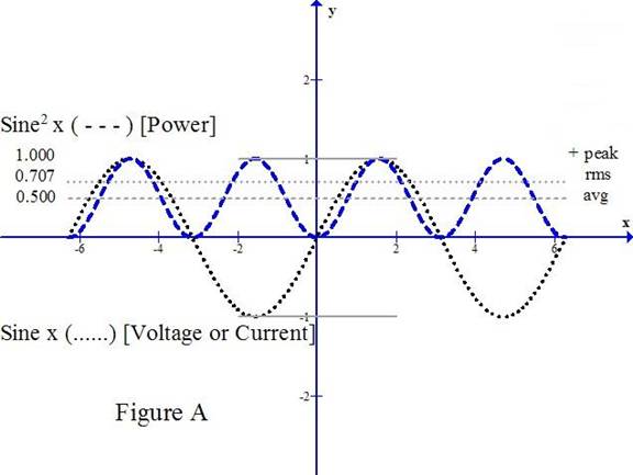
AC or alternating current that powers your home or office most commonly is generated from rotating machinery such as alternators. As the rotor turns and its pole piece passes from one stator coil to another, it produces power whose voltage or current follows a sine waveshape. The big DOTTED curve in Figure A is a sine waveform for voltage or current. A “pure” waveform is important to the power utility to keep system losses low.
The instantaneous value at one point in time may start at zero, rise smoothly to a positive peak, decline to zero, and progress toward an equal negative peak value, then rise back toward zero, and repeat this process, which we call a cycle. Figure A illustrates 2 cycles with time increasing to the right. In the U.S. these cycles occur 60 times per second and we refer to this as 60 HERTZ, where a HERTZ is a cycle per second. At 60 Hz., each cycle takes 1/60th of a second or 0.0167 seconds or 16.7 milliseconds (16.7 thousandths of a second). In Europe and in those countries that follow its standard, the standard voltage is about 220 and the line frequency is 50 Hz., and the cycle lasts 0.020 seconds.
There are 3 easy-to-find, fixed parts of a sine waveform for voltage or current: the POSITIVE PEAK, the NEGATIVE PEAK, and where the waveform CROSSES ZERO (twice per cycle). However, these are not convenient to use when we are interested in measuring power, which is work. Most appliances operate only on AC. However, there are some that will operate on either AC or DC. For example, it might be an iron or a toaster. Since alternating current is always continuously varying in time, we need a value for the AC that can produce the same amount of power that an equivalent DC (direct current) value that would produce. So, if we put 100 volts DC into a heating element and it developed a certain amount of heat (calories), what would be the amount of alternating current that would provide the same amount of heat. This would be defined as 100 volts AC rms. Here’s how. (It gets deep here.)
Power is calculated as W= E x I, or W = E2 / R, or W= I2 x R where ( W ) represents power in watts, ( E ) represents voltage in volts, ( I ) represents current in amperes, and ( R ) resistance in ohms. Voltage is like pressure which forces electrons to flow. Current is a measure of the quantity of electrons flowing and resistance is a measure of the circuit’s resistance to current flow. This is much like the water hose that you use in the yard. The voltage is like the water pressure. The more the pressure, the farther the water will spray. The electrical current is analogous to the quantity of water that flows. Electrical resistance is analogous to resistance to water flow – a smaller or longer hose has more resistance and less water flows. And the combination of pressure and flow represents work.
Pressure (volts) times quantity of electrons (amperes or amps.) flowing is a measure of work done, or power. You will notice that power is a squared value from the relations E x E, I x I, or E x I. So if we take the sine waveform and square it (see the DASHED curve in Fig. A), we will get a new sine waveform of twice the frequency. (When we say squared here, we mean the magnitude of each part of the sine curve is multiplied by itself to produce the corresponding part of the sine-squared curve.)
Instead of swinging symmetrically around zero, as does voltage or current, its lowest peak is at zero (corresponding to the zero- crossing of the voltage or current waveform) [0 times 0 = 0] and its highest peak is the square of the most positive or negative peak of the voltage or current waveform. The power waveform is always positive. (a (+) value times a (+) value is always (+), and a (–) value times a (–) value is also (+)). Yes, a (+) value times a (–) value is (-).) We may touch on that later when we are discussing UPS’s.
The “mean” value (average) of the mathematically squared waveform (not a clipped waveform) is halfway between zero and the most positive peak (see Fig. A). If we had a DC voltage equivalent to the AC value, when squared, it would lie at the same level as the mean or average of the AC squared waveform.
Now to find what this voltage is. Since the power waveform is a squared value, to get the value that is squared (the voltage or current), we can take the square root of the mean of the squared value. Hence we get the rms or root mean square. In practice with a pure sine waveform, the rms value is (½ of the square root of 2) or 0.707 times the peak value. Correspondingly, the peak value is the square root of 2 times the rms value or 1.414. But this applies ONLY to sine waveforms, as you will see later. See, that wasn’t so bad.
Surge Arrestors
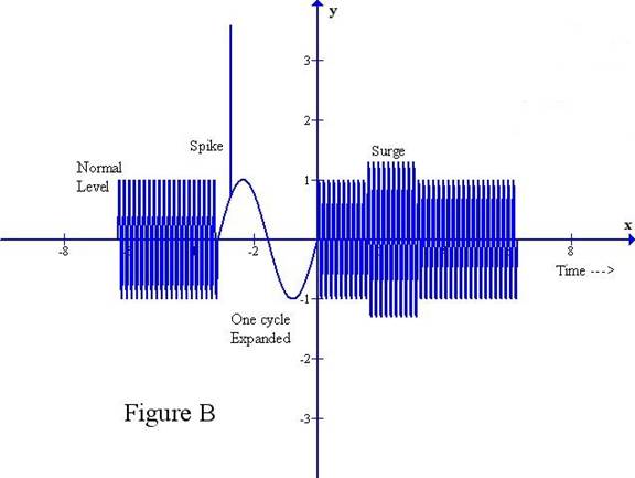
By the way, I am going to define surges and spikes in a manner that may or may not be the way that others do. To me, a spike is a voltage transient that has a duration that is substantially less than 1 cycle of the AC while, to me, a surge is a group of 2 or more cycles of AC whose voltage is greater than the normal value. See Figure B, above.
Let’s now talk about surge arrestors and we’ll use some of this new found knowledge. Let’s start with 125 volts rms as the maximum RATED value. The rated voltage is the maximum sustained voltage that is safe to apply to the device as determined by the manufacturer (who certainly ought to know best). We need to know the peak value of this. So with our newfound knowledge above, we multiply the rms value by the square root of 2, or 1.414, and get 176.7 volts peak. Why is this important? For a surge arrestor, we want to provide a limiter that will pass peak voltages up to the rated peak value, but will not permit it to exceed the safe maximum value that it should handle. So, early surge arrestors for 125 v rms service had a clipping value of around 180 to 200 volts (more than the 176.7 value). However, the Underwriters Labs in 1996 established a transient voltage suppression standard that 125 volt rms rated equipment must be able to tolerate transients up to 380 volts peak without damage. Of all the nameplate data that I was able to examine, to be in compliance with the UL standard, surge arrestors now are designed to limit spikes and surges to 330 volts peak which is safely less than the 380 volt peaks that UL rated equipment must tolerate.
Time, nano-seconds, varistors, joule, watt
Before we go further, we need to think about TIME – very small increments of time – down in the nano-second range. We used to think that a microsecond, a millionth of a second, was a very small unit of time. Now, a nano-second, which is a thousandth of a microsecond (a billionth of a second) is common. Why is this important? Because the semiconductor integrated circuits in the computer including the CPU are so fast now that they can respond to signals that are even less than a nano-second. Dimensions on computer chips are measured in millionths of an inch and their operating voltages may be in the order of 2 to 3 volts. If we have spikes that are in the nano-second range, the IC’s can not only respond to them, they can be destroyed. So our surge arrestor has to be fast, very fast, to snub down fast spikes before they can crash through and destroy our IC’s. Luckily, scientists have invented MOV’s (metal-oxide-varistors) which happen to be just the kind of device we need. Up to a certain voltage, they act as an insulator, and above it they conduct until the applied voltage falls back below the rated conducting voltage. And, they are very fast. They can start conducting very quickly as soon as the conducting voltage is exceeded – in a nano-second or less. And, they can conduct heavy currents.
Let’s take a look at some of the nameplate data from a surge arrestor several years old. This one is a Belkin SurgeMaster F5C572-TEL. It has 7 surge protected outlets plus telephone line protection. We will assume that it is typical of surge protection available since a few years ago. We will list the name-plate data and try to see what this means
“Complies with 1998 UL 1449 rating of 330 volts peak.
Maximum energy dissipation : 752 joules (whole unit - all combinations combined)
H-N (hot to neutral) 240 joules
H-G (hot to ground) 176 joules
N-G (neutral to ground) 176 joules
Phone line 160 joules Protects phone, fax, and modem equipment
Response time: < 1 nano-second
Electrical Rating:
125V, 15A, 60Hz, 1875 watts continuous duty.
Maximum spike current 22,000 amperes
H-N 9,000 amperes
H-G 6,500 amperes
N-G 6,500 amperes
EMI/RFI Filtration
Noise reduction 100 Khz to 100 Mhz Attenuation up to 50 dB”
And the unit is equipped with a 6 foot power cord.
So, what does this mean?
A joule is a watt-second. That is, a watt of power dissipated for a second, such as 1 volt and 1 amp. But 10 watts for 1/10th second would also be a joule. How about 1000 watts for 1/1000th of a second. You have undoubtedly seen a 1000 watt steam iron or a 700 watt microwave oven. The wattage is a measure of how much heat the unit produces or, in the case of a motor, how much horsepower it produces. 1 horsepower corresponds to 746 watts, if you are interested. As a unit of power, a joule or watt-second is equivalent to about 1/1000 btu (British Thermal Units).
Let’s take the 752 total joule rating and divide it by 330 volts, the clipping voltage.
(752 joules divided by 330 volts peak = 2.2 amps total spike current lasting for 1 second)
(240 joules divided by 330 volts peak = 0.73 amps) hot to neutral
(176 joules divided by 330 volts peak = 0.53 amps) hot to ground and neutral to ground and
(160 joules divided by 330 volts peak = 0.48 amps for the phone line)
The above figures assume a one second duration. The spike current figures are based upon the maximum current that can be applied to the surge arrestor without permanent damage. Based upon these maximum current values, let’s see what the spike duration might be.
Maximum “spike current” 22000 amperes (whole unit combined). (Maximum current before fusing occurs.) (2.2 amps /22000 amps) = 0.0001second or 100 microseconds
These ratings are maxima for the whole unit.
For individual conductor pairings:
For H-N, 0.73/9000 = 81 microseconds
For H-G and N-G ), .53/6500 = 82 microseconds
The phone line lacks a peak current rating so we can’t explicitly calculate the duration. However, it probably is in the range of 80-100 microseconds.
The noise reduction specification to me is somewhat weasely since it says “up to” etc. However, 50 db is not trivial. Where it can be achieved, this amounts to a voltage ratio of 316:1 or a power ratio of 100,000:1. So, there can be a substantial reduction in spike energy.
This is not the whole story. This just tells how much difference in potential between conductors at the surge arrestor is permitted. It does NOT address how much potential there could be between the surge arrestor as a whole together with the connected system and the floor or local ground and thus personal risk. We’ll be talking about this shortly. And, we haven’t addressed the significance of the length of the power cord, either.
How do they work? There are two types of surge arrestors: shunt and series, with the shunt type being far and away the most common, and the one we will discuss. For the shunt type, an MOV or metal-oxide varistor is connected between each of the 3 pairs of conductors as H-N, H-G, or N-G to prevent the voltage between each pairing of conductors from exceeding 330 volts peak.
Most of the better surge arrestors are also equipped with circuit breakers so if the surge lasts for more than a few tenths of a second, the circuit breaker will trip to protect the MOV’s against burnout as well as the equipment protected. In addition, some of the surge arrestors include line “noise” filters to help suppress conducted line noise.
Circuit breakers, magnetic, thermal
Let’s talk about circuit breakers for a moment since we just mentioned them. Most homes and offices are protected by them. There are 2 principal types: magnetic and thermal. These are electro-mechanical devices which mechanically open a contact. For most circuits, magnetic breakers are used because they will trip whenever the rated current is exceeded. Trip times can vary from a few milliseconds to generally less than one second. (A millisecond is 1/1000th of a second or 1000 microseconds.)
Thermal circuit breakers are used to protect circuits using motors. Most electric motors have “starting” currents that are much higher than their “run” current. This is especially true for motors that drive compressors such as air-conditioners. Most of these start and come up to speed in a relatively short time, such as 1 or 2 seconds. Thermal breakers typically pass current through a bi-metallic strip that bends if the current is high enough to cause its temperature to rise. The bending is dependent on an I2 x t relationship. ( Heavy current for a short time, or lesser current for a longer time, may or may not produce enough heating to bend the strip.) These allow a heavy starting current for the motor to flow for a short time but stay closed as the current drops back quickly to a much lower “run current”. A sustained current beyond the rating will cause it to trip. These circuit breakers are relatively slow. If the trip current is just barely above the rated value, trip time can be a number of seconds. The higher the trip current, relative to its rated value, the faster the breaker will trip, down to perhaps a second or two. So, circuit breakers for air conditioners should employ the thermal type, while breakers for lamps and non-motorized appliances should use the magnetic type.
But, you remember our discussion above, about “nano-seconds”? So, you can see that circuit breakers are intended to protect house or office wiring against excessive currents to prevent fires but they are not intended or capable of protecting electronic equipment.
Their many milliseconds response time is just too slow for circuits that respond in nano-seconds.
Intimidating Theory #2, reactance, impedance
Most general power circuits are, as we have said, intended to support lighting, motors, and other appliances where speed or high frequencies are not a matter of concern. Most electronic equipment is designed to operate in the fast lane. Remember the nano second discussion above? Time or speed is a very important consideration with most electronics.
When we deal with DC circuits, voltage (E or V), current (I), and resistance ( R ) and of course power or watts ( W ) is all we have to deal with. E = I x R, I = E / R, R = E / I and W = E x I, etc.
However, when we deal with alternating current circuits and transient or changing voltages or current, another term comes into play – REACTANCE (X). Resistance is no longer the only term that resists current flow. Now we have to consider the effect of reactance as well. The composite relation, resistance and reactance, is referred to as IMPEDANCE.
All conductors and coils possess inductance, which we define as positive reactance. These STORE ENERGY in the form of a magnetic field. Current flow in a conductor produces a magnetic field which surrounds it. Coils concentrate this magnetic field. All conductors and conducting surfaces also have a property called capacitance in which ELECTRICAL ENERGY IS STORED as a charge between 2 conductors or conducting surfaces. We define capacitive reactance as negative reactance. So reactance is a measure of energy storage. But inductance and capacitance act essentially in opposite fashion. At any particular specific frequency, the net reactance, X, is the sum of the plus and minus reactance values. The magnitude of the impedance (Z ) = square root of (R2 + X2) and this is what controls current flow in the fast lane.
The importance of this will become apparent shortly. But before we leave this, we need to understand that the inductive reactance rises with frequency. So as the frequency rises so does the inductive reactance. Coils are sometimes called chokes and are used in filters to prevent or restrict the flow of high frequency currents. As inductive reactance increases with frequency, capacitive reactance decreases. So, sometimes in filters we place a choke in series and a capacitor in shunt after the choke to filter or snub down high frequency signals or noise. Fast pulses or spikes have a lot of high frequency energy that one wants to control. We’ll dwell on that shortly. This pretty well concludes this part of intimidating theory.
Lightning, conducting, induced
Now let’s get into the nitty-gritty. We’re going to jump ahead to lightning. You have certainly seen lightning, plenty of it, and in some cases have seen the results. Lightning is caused when electrical charges accumulate on the water droplets in clouds. The clouds and the earth act like a giant capacitor. When the charges build up to the point that the atmosphere between the earth and the clouds can no longer provide sufficient insulation, the charge is discharged, which we see as lightning and hear as thunder. The voltage to cause the atmosphere to ionize may be many millions of volts. The current in the lightning strike may be tens of thousands of amperes. (a 100 watt light bulb carries about 0.8 amperes by comparison). The energy in a lightning strike is so large that if your home or office sustains a direct strike, unless you have an adequate lightning protective system, that surge arrestor or UPS will not be sufficient to provide needed protection. It is tough to compete with nature.
The lightning stroke is very short in duration and the current increases in magnitude very rapidly. We say it has a very short rise-time. The energy conveyed to earth occurs in two forms: conductive and inductive. Both can destroy equipment. The conductive form is conveyed directly via wiring. Conductive energy is so large that it is not uncommon for fusing or melting to occur. Or, lightning strikes a tree, the current heats the moisture in the trunk to steam almost instantly, and the trunk explodes. A nearby conductive strike conveys so much energy that a conventional surge arrestor probably will be unable to control its effects. A strike some distance away may produce spikes or surges that a surge arrestor can handle. A good ground can help the surge arrestor protect your system.
For lightning protection, especially if one is in a circumstance where lightning strikes are likely, then things such as lightning rods, grounds, and lightning arrestors may be needed. The details of such are beyond the scope of this discussion.
A very insidious form of energy from a lightning strike is the inductive energy and one that sneakily destroys a lot of electronic equipment. When the lightning strikes, a very heavy short term current is conducted. This creates a magnetic field like a radio transmitter. Every conductor in the vicinity acts like an antenna that picks up some of this electromagnetic energy. The longer the conductor is and the closer to the strike, the higher the energy and voltage induced in this conductor. This also critically needs to be controlled.
For purposes of discussion about effects of lightning, we’ll use for our example a single story ranch-style residence with a concrete slab, which is very common along the Gulf Coast. We will also presume that lightning strikes are not likely to the residence but to power poles or trees. In this configuration, the circuit breaker panel is near or at the rear of this residence in order to be near the power line. Transformers are mounted on the power pole behind the house next door. And, we will place the computer near the front of the home in the study or a front bedroom, a long way from the circuit breaker panel.
So, the length of wire from the breaker panel to the outlet in the front bedroom where the computer is wired is about 100 ft. Where power is brought into the house at the breaker panel, the neutral is grounded close to the breaker panel. Most homes are supplied with 235 volts, center tapped, so that there is about 117 volts between the center tap and each of the two outside legs and 235 volts between the two outside legs. The center tap, or neutral, in compliance with the building code, is grounded at the breaker panel. Thus each outside leg or hot lead is no more than 117 volts from ground. Remember, due to the chemicals in concrete, the concrete slab is a grounded conductor. It may not be a good enough conductor to power a motor but it is plenty good enough to be a safety hazard if you are standing on it and touch a hot lead. (It only takes a few milliamperes, thousandths of an ampere, to hurt you.)
If lightning strikes a tree or the power pole nearby, the 100 ft. of wiring can act as a significant “antenna” and the voltage at the power outlet where the computer is connected can be quite high relative to the concrete floor. If you have a telephone cable brought there for a dial-up or DSL connection, it acts like an antenna also. If one is sitting at the computer when lightning strikes, they could be at risk unless we do something about it.
The obvious solution is to provide an effective ground, very, very close to the electric outlet supplying power to the computer. The objective is to supply a low impedance ground connection that will be at the same potential as the concrete slab in that vicinity. Yes, you can have a very significant difference in potential across the slab between the front and back of the residence. The ground, way back at the breaker panel, good for low frequencies such as 60 Hz, is too far away for this purpose. Now we are trying to be able to snub down lightning-induced energy that would be hazardous to humans and electronic equipment. How do we do this?
Grounds and grounding
One good way is to power the computer from an electrical outlet on the outside wall of the residence and, outside of which, we drive a ground rod 8 to 12 feet long. We remove the electric outlet from its mounting box, drill a hole through the back of the box and through the wall of the house. Then we connect a short piece of heavy wire, say 10 gauge, between the ground terminal of the electrical outlet and the ground rod. A short heavy connection between the outlet and the ground rod is very important. Short because we don’t want the length to act as much of an antenna. Heavy because we want a low resistance and low inductance connection, thus low impedance.
Then the surge arrestor has a low impedance path to convey surge currents to ground.
If we depended on the wiring from the breaker panel, the difference in potential between conductors, hot, neutral, and the ground lead, might not be too much but, at the outlet, the potential between the connections at the outlet could be very high relative to the concrete slab due both to the antenna effect of 100 feet of wire and the relatively high impedance of this long length of wire. Surge arrestors might not be able to snub down this induced potential due to ineffectual grounding. Let me emphasize that we can measure the DC resistance between the ground wire and the neutral which are tied together at the breaker and the value may be very low, say less than 1 ohm. But the impedance of this 200 foot loop at high frequencies could be several hundred ohms – not a good way to suppress a lightning strike.
Now, let’s talk about SINGLE POINT GROUNDING.
Single point grounding is a very important concept, widely used in individual equipment and on complex systems. We really want everything in our computer system to be tied to the SAME ground point. Electrically, then everything in our system will “move together”. If we have induced voltages, then everything will be at the same potential and we won’t have significant differences in potential between various elements of our computer system. If we ground various elements to different grounds, then we can experience significant differences in potential between elements of our system and thus risk damage. This thru-the-wall ground connection is our single point ground. And, in general we have two sockets on the outlet to connect surge suppressors or UPS to. Do NOT, I repeat, do NOT connect any portion of your computer system to any other outlet. Everything must connect through this one outlet. You can find a 6 outlet expander that will replace the outlet plate, that will plug into the outlet and provide the means to accept up to 6 power plugs at this one location.
Uninterruptible Power Supplies (ups), off-line, on-line, ampere-hours, volt-amps
There are basically 2 types of UPS: OFFLINE or STANDBY, and ONLINE or CONTINUOUS. The OFFLINE OR STANDBY UPS, in normal operation, passes line power through a surge suppressor and a power switch to its load outlets. When line power is present, the internal battery is charged. When power fails, power detection circuitry detects failure, switches the power connection from line power to its internal battery driven power inverter and turns on the inverter. There will a small glitch in the power supplied to its load due to power failure detection and switchover to inverter operation. This small glitch, if it is not much more than 8.3 milliseconds, is generally not a problem. Most equipment power supplies employ full wave rectification of the 60 Hz power. ½ half cycle of the 60 HZ waveform is 8.3 milliseconds and the power supplies have filters that will bridge this time interval. So main power in the equipment won’t sag enough in 8 milliseconds to cause a problem due to switchover time.
The size of the battery (ampere hours) and the load you place on it will determine how long the UPS will generate AC power before the charge on the battery is exhausted.
Capacities of 200 Volt-Amps to 1500 Volt-amps are readily available in standby UPS’s.
If the UPS is to be used only to stay up long enough for your computer to shut down safely, a relatively small one should suffice and only the computer itself and the monitor need be connected.
If your UPS is to stay up long enough for your auxiliary generator to start and come up to speed, it must support your entire computer system and its capacity in VOLT-AMPS must be sufficient.
The on-line or continuous UPS is a different beast. This device runs off the battery at all times. Line power is used solely to recharge and keep the battery charged. Your entire system is plugged into the UPS. Its capacity must be big enough to support your entire system for as long as you need it to operate or until you can start an auxiliary generator to keep the batteries charged.
Since your system normally runs off the inverter which is powered by the battery, surge suppression is not as important. However, if line power can be passed through so that the inverter can be turned off for service or test, then surge suppression is required. Check that the UPS is equipped with surge suppression.
In general, the on-line or continuous UPS are considerably more expensive than an equivalent capacity off-line UPS. Capacities of 3000 volt-amps to 100’s of thousands of volt – amps are available.
Intimidating Theory #3
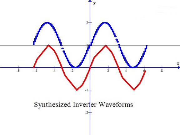
Now we come to a necessary but delicate subject. Sizing the UPS. And we come to Intimidating Theory #3. Most computer equipment is powered by switching supplies. These do not conduct continuously, but in a succession of short pulses. The higher the line voltage, the shorter these pulses. OK, what’s the problem? The problem is how we measure the line current from each device, so we can add up the total current that the UPS has to supply. At least one author suggests that the best method is to use a meter to measure the line current. His alternative is to use manufacturer’s name-plate data. I have to take issue with this and suggest using the manufacturer’s name plate data. Why? Because almost all commercially made meters are calibrated based on sine-wave current. Unfortunately the current drawn by computer components is not sine-wave (see above graph) and, as such, the readings by most meters can be only slightly better than meaningless. Most meters internally sense the average value of the AC sinewave (63.2% of the peak value) and their display is 111% of this value which reads in rms. The more expensive meters read in true rms which is 70.7% of the peak value of the sine wave. But what if it isn’t sine wave? And it isn’t! Presumably the manufacturer’s values, by whatever means they use, is more indicative. In any case, my recommendation, to be on the safe side, would be to take the manufacturer’s volt-amp ratings, add them up, add at least 20-30 % and select a volt-amp rating above this value.
Phase, Power factor
You may notice that most UPS’s have dual ratings of volt-amps and watts with the volt-amps rating being higher. This is because of something that we alluded to earlier but did not discuss. If our loads were purely resistive, as in an iron, then the AC current would rise and fall as the AC voltage does. We would say that the current is in phase with the voltage. This is also referred to as 100% power factor.
Unfortunately, most power supplies are not resistive in nature. Some tend to be capacitive and others inductive. This means that the current waveform either leads or lags the voltage waveform. True power is the portion of the two waveforms that are coincident, as E x I x cosine (theta), where theta is the phase angle between the two waveforms. Since cosine (theta) is a maximum of 1 when theta is zero, power can only be as much as the volt-amps, or less. And, of course, this presumes sine waveforms. For non-sinusoidal waveforms, calculation becomes much, much more complicated.
Volt-amps, the larger figure, is the measure of stress on the system, and watts is the measure of the true power delivered.
The key here is that the UPS has the volt-amp capacity to support the volt-amp load of all the devices that have to operate from the UPS.
One additional point: The length of the power cord. I have seen them vary from 6 to 12 feet or more. If you recall the discussion above about impedance and grounds, for this reason the shorter power cord, while perhaps less convenient, will have a lower impedance ground lead and thus better suppression of spikes and surges.
One last point that needs to be included is TESTING YOUR UPS. Why? The battery in the UPS deteriorates over time. The UPS needs to be tested under load. So, to do this, protect your data by doing a normal shutdown of your computer. Then, boot it up but do not click on or initiate any program. Leave it in an idle state. Then, PULL THE AC POWER PLUG. See if the system stays up, operating for the time you expect. Then plug in the supply. When the “UP TIME” decreases to less than you need, it probably is time to replace the battery. This test should be performed at least once a month. It would be a disaster for you if you had a power failure, your battery had gone west, you were unaware of it, and your UPS wasn’t able to do what you bought it for.
Corrosion or thermal loosening of electric outlet screws.
You may recall a long time ago we described “daisy-chaining” when conductors from the circuit breaker panel connect to the first electrical fixture, then from there to the next, etc. With 4 such fixtures, each with 4 screws, we could have a circuit with 16 screw terminal connections. We would be lucky if all 16 or more terminals remain tight. Unfortunately, there is a mechanism that all of us are subject to that can cause some of them to loosen. The wire we use today is copper. The screws are brass. Their coefficients of thermal expansion are similar but are not the same. Over time, temperature changes can cause some of them to work loose. If your lights blink frequently, it might be in your best interests to retighten all of these screws on each circuit that blinks. It is necessary to remake the metal-to-metal contact at each joint. The sneaky part here is that the load could be at the farthest part of the circuit from the breaker panel. Yet the loosened terminal could be in the wall closer to the breaker panel with nothing plugged into it. As the terminal loosens, the joint resistance increases. But (I x I x R) is heat. The process is progressive. More heat causes more loosening, which causes more resistance and more heat. Ultimately the terminal can get hot enough to initiate a fire. If the circuit has lamps that blink, have it checked. If you hear an outlet buzzing, check it soon!
Another subtle item is corrosion on the conductors that bring power to your home. Very often there are splices with the two pieces joined with a crimp connector. Over time, especially if exposed to weather, this can corrode, weakening the connection. If the splice is in the neutral, then a very weird effect can occur. The resistance causes a voltage drop dependent on the current flowing. If the load is not balanced, that is, the load on one of the hot conductors is higher than the load on the other, there will be a voltage DROP on the circuit with the heavier load and there will be a voltage RISE on circuits connected to the other hot lead. If you measure more than about 3 to 5 volts difference in the two line-to-neutral voltages, contact the electrical utility and have the power lines checked. If this goes on too long and this unbalance gets too large, motors on the low side can burn out because they don’t have enough power to support their load and they keep trying to run on their start winding. Items on the high side can burn out do to excessive voltage. Incandescent bulb life can be materially shortened on excessive voltage. Their life is dependent on the 4th power of the voltage. Yes, 130 volt rated lamps will last longer on 117 v ac but won’t provide as much light intensity. Where do you think long life bulbs come from?
So there you have it. AC 101. You have plowed your way to get here.
Summary
For safe operation and maximum protection:
- Install a good ground within a few feet of, and connect it to the outlet that powers your computer. This is for you and your computer’s safety!
- Use this outlet only for ALL the components of your computer system.
- Use a good surge arrestor or UPS (Uninterruptible Power Supply)
- Select a unit with a short power cord – not over 6 ft. if you can
- If you backup frequently (every 5 minutes or so) and can tolerate losing the last 5 minutes of your work, just use a good surge arrestor
- If you have a mission-critical operation and cannot stop operating, select a UPS with enough capacity to support your entire system long enough for an emergency alternator to be started and brought up to speed
- If you can’t afford loss of your work but do not have to continue operating during a power failure, select a UPS with automatic shutdown via a USB port and enough capacity to support only your CPU and monitor for the time it takes for your system to go thru its normal shutdown. Do not include peripherals such as printer, scanner, etc. Test it every month.
- When you select a surge arrestor or UPS, make sure it affords protection capability for the phone line to protect your phone, fax, and modem
- If your situation is prone to lightning strikes, get a lightning rod, lightning arrestor, and separate ground rod. Do NOT share this “lightning” ground rod with anything else.
- If your lights blink, retighten all the screws on the electrical outlets in that power circuit all the way back to the circuit breaker panel
- If you notice that the voltage on power circuits is low on some outlets and high on others, contact the power company and have them check the power brought into your home or office all the way from the pole to your circuit breaker panel. The neutral connection from the power pole may be corroded or loose.
- During a lightning storm, it is still safest, even with all your protective devices, to step away from your system, and wait until the storm passes.
(Curves drawn using free program GRAPH 4.1 from WWW.PADOWAN.DK)
|